Español
 Русский
 Tiếng Việt
 中文
中文 suomi
suomi Français
 Português
 English
 Deutsch
 Français
 Español
 Italiano
 Português
 Pусский
1. Chilled water pump:
A device that drives water to circulate in a chilled water loop. We know that the ends of the air-conditioned room (such as fan coils, air handling units, etc.) need cold water provided by the chiller, but the chilled water will not flow naturally due to resistance limitations, which requires a water pump to drive the chilled water to circulate to achieve replacement. hot purpose.
2. Cooling water pump:
A device that drives water to circulate in a cooling water loop. We know that the cooling water takes away part of the heat of the refrigerant after entering the chiller, and then flows to the cooling tower to release this part of the heat. The cooling water pump is responsible for driving the cooling water to circulate in the closed loop between the unit and the cooling tower. The appearance is the same as that of a chilled water pump.
3. Water replenishment pump:
The device used for air conditioner water replenishment is responsible for pumping processed softened water into the system. The appearance is the same as the water pump above. Commonly used water pumps include:
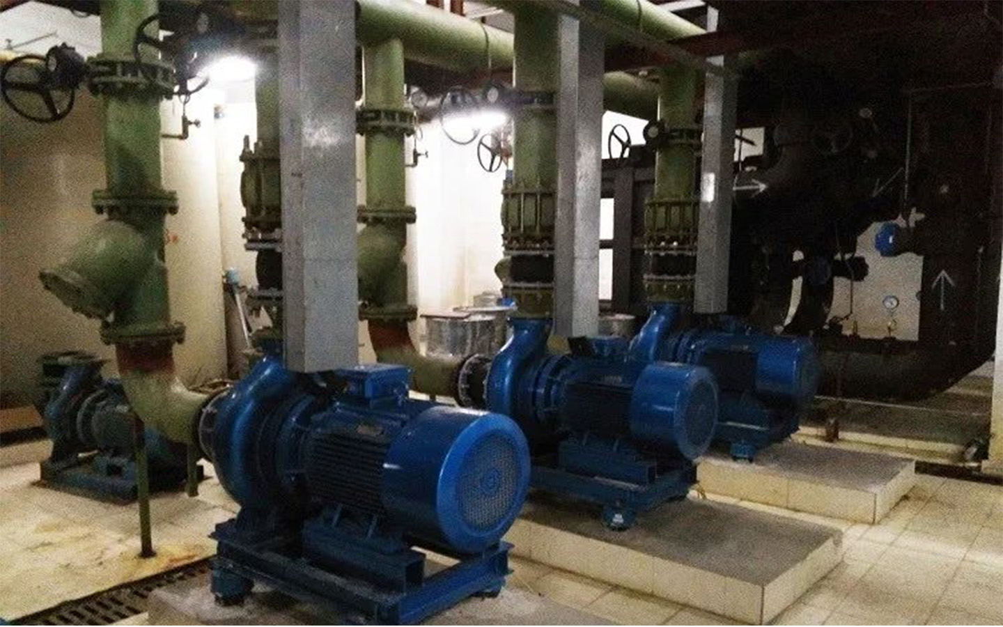
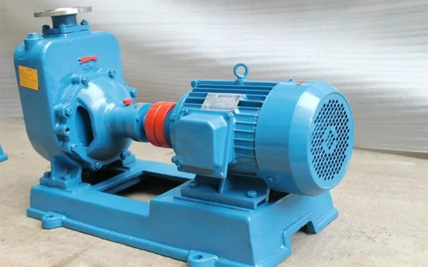
Horizontal centrifugal pump
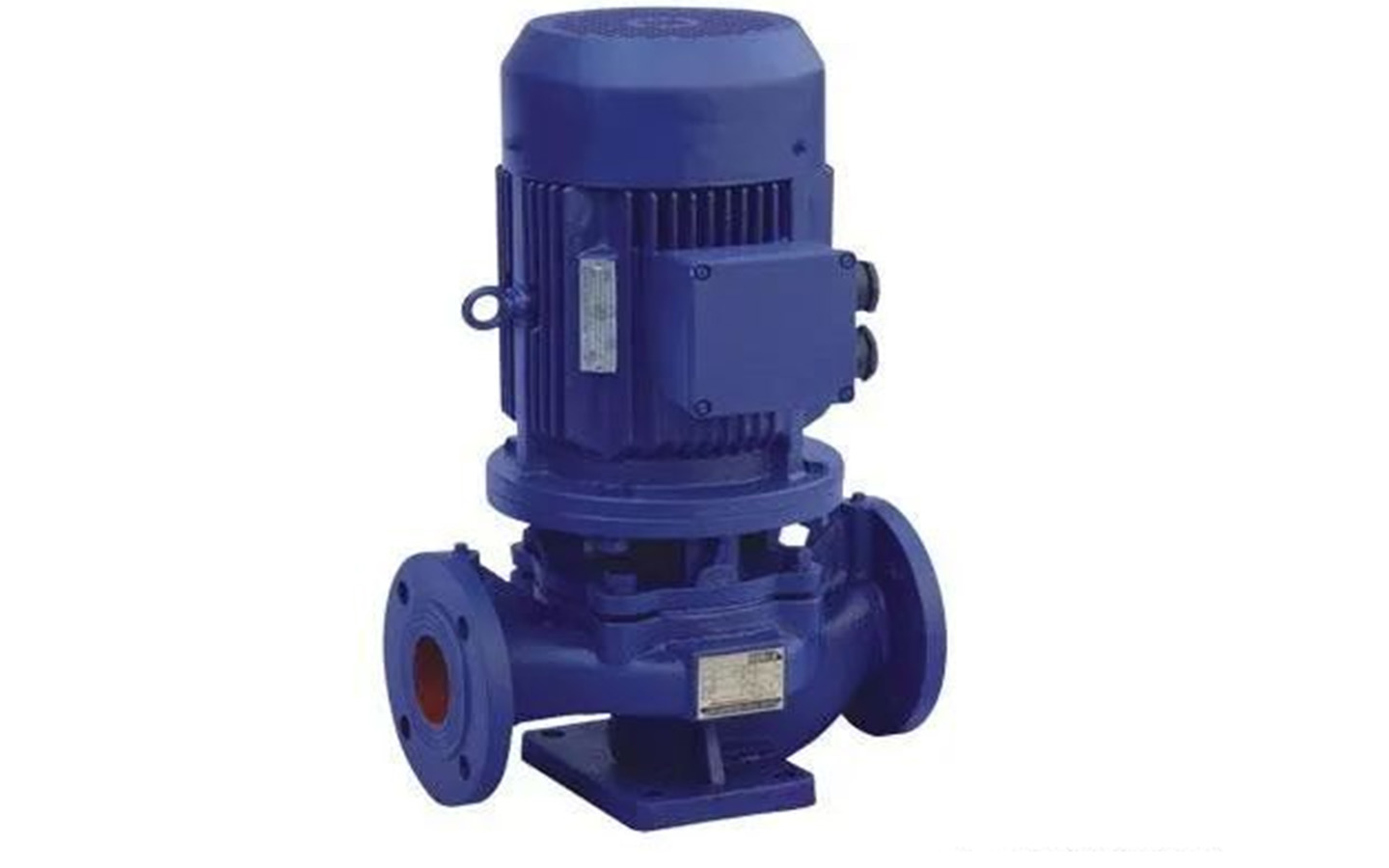
vertical centrifugal pump
These two types of centrifugal pumps can be used in chilled water systems, cooling water systems and water replenishment systems. Horizontal centrifugal pumps can be used in places with a large machine room area, and vertical centrifugal pumps can be considered in places with a smaller machine room area.
When the water pumps are running in parallel, the flow rate will be attenuated; when the number of parallel pumps exceeds 3, the attenuation will be particularly severe. Therefore it is recommended:
·When selecting multiple water pumps, the attenuation of the flow rate must be considered, and a margin of 5% to 10% is generally added.
·It is not advisable to connect more than 3 water pumps in parallel, that is, when selecting a refrigeration host, it is not advisable to connect more than three water pumps in parallel.
·Large and medium-sized projects should be equipped with cold and hot water circulation pumps respectively.
Generally, the number of chilled water pumps and cooling water pumps should correspond to the refrigeration host, and one should be considered as a backup. The water replenishment pump is generally selected according to the principle of one for use and one for backup to ensure reliable water replenishment of the system.
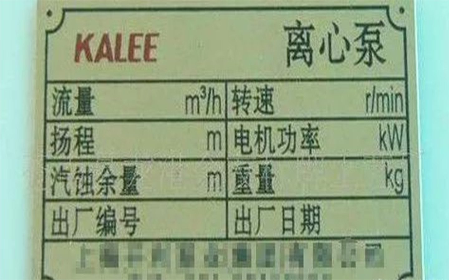
The water pump nameplate generally indicates the rated flow rate and head (shown above). When we choose a water pump, we need to determine the flow rate and lift of the water pump, and then determine the corresponding water pump according to the installation requirements.
4. Calculation of water pump flow rate
(1) Chilled water pump and cooling water pump flow calculation formula:
L(m3/h)=Q(Kw)×(1.15~1.2)/(5℃×1.163);
In the formula: Q—-refrigeration capacity of the refrigeration host, Kw; L—-flow rate of the refrigeration cooling water pump, m3/h
(2) Flow rate of supply water pump:
The normal supply water volume is 1% to 2% of the system’s circulating water volume. However, when selecting a supply water pump, the flow rate of the supply water pump should not only meet the normal supply water volume of the above water system, but also consider the increased supply water volume in the event of an accident. Therefore, The flow rate of the water supply pump is usually not less than 4 times the normal water supply volume. The effective volume of the water supply tank can be considered based on the normal water supply volume of 1 to 1.5 hours.
5. Determination of water pump head
(1) Composition of chilled water pump head:
Refrigeration unit evaporator water resistance: generally 5~7mH2O; (see product sample for details)
Water resistance of terminal equipment (air handling unit, fan coil unit, etc.) surface cooler or evaporator: generally 5~7mH2O; (see product sample for details)
The resistance of return water filters, two-way regulating valves, etc. is generally 3~5mH2O;
Water resistance of water distributor and water collector: generally one is 3mH2O;
Resistance and local resistance loss along the water pipeline of the refrigeration system: generally 7~10mH2O;
To sum up, the chilled water pump head is 26~35mH2O, generally 32~36mH2O.
Note: The calculation of the head should be based on the specific conditions of the refrigeration system and cannot be copied from experience values.
(2) Composition of cooling water pump head:
Refrigeration unit condenser water resistance: generally 5~7mH2O; (for specific values, please refer to the product sample)
Cooling tower nozzle water spray pressure: generally 2~3mH2O;
The height difference from the water tray to the nozzle of the cooling tower (open cooling tower): generally 2~3mH2O;
The resistance of return water filters, two-way regulating valves, etc. is generally 3~5mH2O;
The resistance and local resistance loss along the water pipeline of the refrigeration system: generally 5~8mH2O;
To sum up, the cooling water pump head is 17~26mH2O, generally 21~25mH2O.
3) Water replenishing pump head:
The head is the distance between the constant pressure point and the highest point + the resistance of the water pump suction end and outlet end + the sufficient head of 3 ~ 5mH2O.
Example: A high-rise building about 100m high is equipped with several water-cooled screws and uses a closed air-conditioning water system. Try to estimate the lift required by the chilled water pump.
Answer:
(1). Chiller evaporator resistance: check the product catalog, 60 kPa (6m water column);
(2). Pipeline resistance: Take the resistance of the dirt collector, water collector, water distributor and pipelines in the refrigerator room to be 50 kPa; take the length of the pipeline on the transmission and distribution side to be 300m and the specific friction resistance to be 300 Pa/m, then The friction resistance is 300*300=90000 Pa=90 kPa; if the local resistance on the transmission and distribution side is 50% of the friction resistance, the local resistance is 90 kPa*0.5=45 kPa; the total resistance of the system pipeline is 50 kPa+ 90 kPa+45 kPa=185 kPa (18.5m water column);
(3). Air conditioning terminal device resistance: The resistance of the air handling unit is generally greater than the resistance of the fan coil unit, so the resistance of the former is 45 kPa (4.5m water column) (can be determined by referring to the product catalog);
(4). The resistance of two-way regulating valve, Y-type filter, etc.: take 40 kPa (4.0m water column).
(5). The sum of the resistance of each part of the water system is: 60 kPa+185kPa+45 kPa+40 kPa=330 kPa (33m water column).
(6). Water pump head: Taking a safety factor of 15%, the head H=33m*1.15=37.95m.
6. Calculation method of water pipeline resistance
①Resistance along the way
The resistance of water along the pipeline: Hf=Rl
In the formula:
Hf——resistance along the water pipe, Pa;
R——Resistance along the unit length, also known as specific friction, Pa/m;
L——The length of the straight section of the water pipe, m.
When the cold water pipe is made of steel pipe or galvanized pipe, the specific friction resistance R is generally 100~400Pa/m, and the most commonly used one is 250Pa/m. Specific friction is a quantity related to water pipe diameter, water flow velocity and flow rate, which can be found through the specific friction calculation chart.
②Local resistance:
When water flows and encounters elbows, tees and other accessories, the calculation formula for local resistance caused by friction and eddy current energy dissipation is:
Hd=ζ×(ρ×V2/2)
In the formula, ζ——local resistance coefficient, V——water velocity, m/s.
③Total resistance of water pipes
The total resistance H (Pa) of water flow includes resistance along the way Hf and local resistance Hd, that is:
H=Hf+Hd