Español
 Русский
 Tiếng Việt
 中文
中文 suomi
suomi Français
 Português
 English
 Deutsch
 Français
 Español
 Italiano
 Português
 Pусский
1. Fan uses and characteristics
1.1 Fan principle
The multi-stage centrifugal blower uses a high-speed rotating impeller to do work on the gas, which increases the gas pressure and speed. The gas with a certain pressure flows out from the edge of the impeller at a higher speed and flows into the diffuser. The gas speed decreases and part of the kinetic energy of the gas is It is converted into potential energy, so that the pressure of the gas continues to increase, and then the gas flows through the bend and the return flow device and enters the next stage compression unit for continued compression; after being compressed by the multi-stage impeller, the gas that reaches the required pressure is collected by the volute It is sent into the system through the exhaust port.
1.2 Purpose and classification
This fan is mainly widely used in various smelting boilers, coal washing plants, mine flotation, sewage treatment, chemical gas production and other occasions that need to transport air. It can also be used to transport other non-corrosive gases, such as blast furnace air supply, sewage treatment aeration Blast, coke oven gas, shaft furnace sintering air supply, etc.
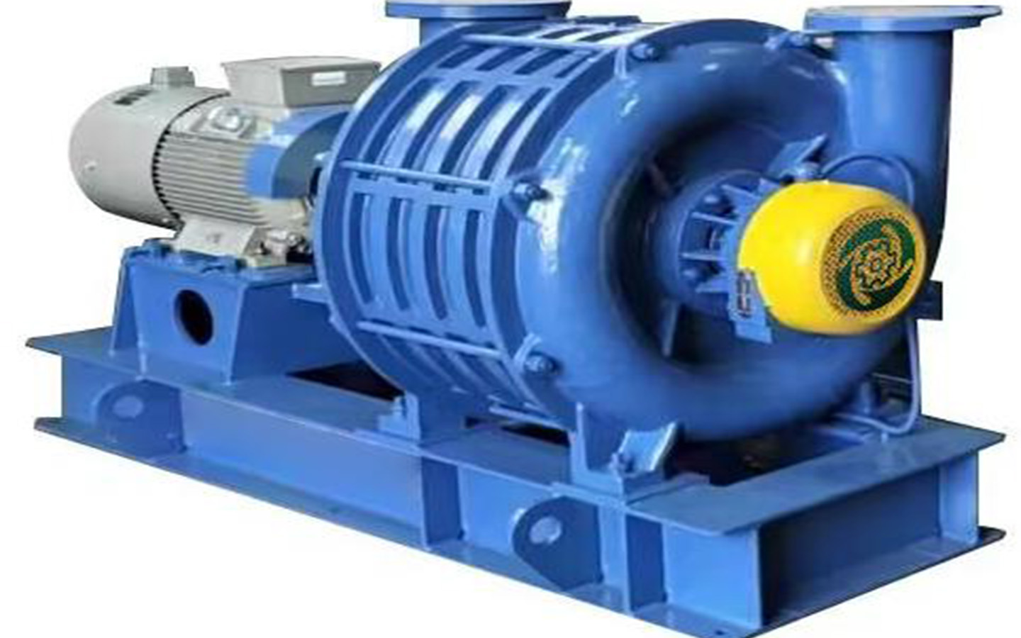
1.3 Structure and technical performance
The main structure of the blower is a cast body, which is composed of an air inlet casing, an air outlet casing and an intermediate casing. Generally, according to the customer’s flow and pressure requirements, the intermediate casings can be combined in series to form a 2 to 8-stage booster fan. Special users can combine it into Level 10, the voltage boost can reach up to 120KPa.
Multi-stage labyrinth seals are used between stages, and multi-stage labyrinth seals and carbon ring combination seals are used at both ends of the inlet and outlet to prevent and reduce leakage to the greatest extent. At the same time, with scientific expansion flow stabilization and reflux devices, the fan efficiency is improved to the highest in the world. Advanced level.
The steel parts of the shaft system are all quenched and tempered, and the aluminum alloy parts such as the impeller are all treated with T6 to ensure the dimensional stability, functional requirements and service life requirements of the processing. After the precision cast aluminum impeller is finished, it is first subjected to static balance verification and then installed on the main shaft in sequence, and then dynamic balance verification is performed. The balance grade is G2.5 (ISO1940), which effectively eliminates harmful vibrations under high-speed operation. produce.
The bearings are of SKF or customer-specified brands, and are lubricated with special bearing lubricating oil and forced air cooling to ensure that the bearings can operate under conditions below 75°C for a long time.
The machine is directly driven by a variable frequency motor, and the blower and motor are directly connected by a coupling. The fan bearings are equipped with temperature and vibration sensors to prevent damage to the fan caused by excessive temperature or increased vibration. At the same time, lifting holes, hooks or lifting rings are installed on the blower body and base to facilitate installation and maintenance.
The fans are tested on the test bench before leaving the factory, and aerodynamic test collection is performed. The data is summarized to form outlet pressure boost, inlet flow and efficiency performance curves, which are filed and saved.
The conventional reference indicators of fans are as follows:
Inlet flow (air volume): When the fan reaches the calibrated speed, the inlet flow generally changes between 75% and 105% of the calibrated flow. When the inlet flow changes from large to small, the boost pressure changes from small to large. When the inlet flow is less than 60% of the rated flow, the fan is prone to surge, resulting in abnormal vibration or impact. This working condition should be avoided. The optimal flow rate of the fan is 80% to 95% of the calibrated flow rate, and a higher output efficiency is desirable.
Outlet voltage boost: The outlet voltage boost increases as the setting value of the frequency modulation motor increases. After frequency modulation, it is best to set it within the range of 80% to 100% of the rated voltage boost value. When the optimal flow rate of the fan is 80% of the calibrated flow rate Under ~95% working conditions, the corresponding range of the boost value is 87%~100% of the rated boost value.
Outlet temperature: The input medium is generally air at room temperature. If the medium input temperature is higher than 20°C, the output pressure obtained will decrease accordingly; conversely, if the temperature is lower than 20°C, the output pressure obtained will increase, and the shaft power will increase accordingly. , at this time, the motor speed can be appropriately reduced.