Español
 Русский
 Tiếng Việt
 中文
中文 suomi
suomi Français
 Português
 English
 Deutsch
 Français
 Español
 Italiano
 Português
 Pусский
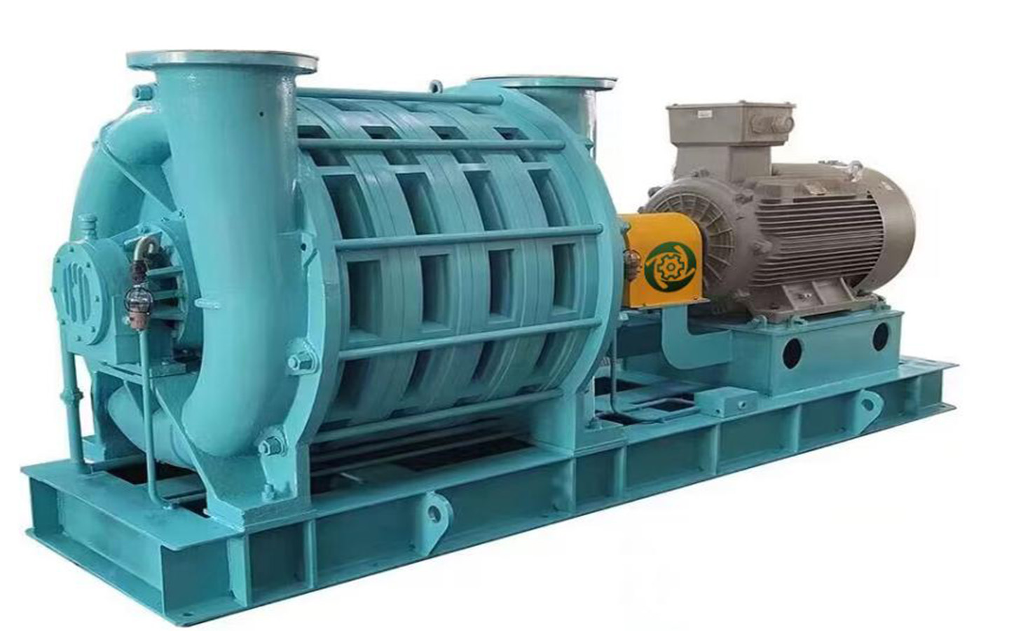
1. Host
1) Fan:
The design and structure of the blower are sturdy and durable, simple to maintain and easy to control. The casing is made of cast iron HT250. It adopts an external bearing structure, in which the impeller is installed on a high-strength main shaft and supported by anti-friction bearings. Bearing design life is at least 30,000 hours (4 years). The fan has a scientifically designed recirculator, guide blades, and a casing with a pressure expansion design to effectively improve the fan efficiency. The non-contact labyrinth seal prevents leakage and ensures that the bearing lubricant is not contaminated. There is no need to disassemble the inlet and outlet pipes when replacing the sealing ring. The entrance and exit are flange-connected and the orientation of the entrance and exit can be selected according to the design requirements. The blower is precision machined from cast iron as a whole. Probes are installed on the bearings at both ends of the fan to measure the bearing temperature and the detection signals are sent to the on-site PLC or user control system for alarm and interlocking shutdown protection.
2) Impeller:
The rotor of this fan is formed by high-strength aluminum alloy casting ZL105A, and the impeller blade path adopts advanced quasi-three-dimensional (ternary flow) design, which greatly improves the operating efficiency of the fan. The impeller undergoes overspeed testing to ensure its mechanical performance. Each impeller undergoes a dynamic balance test. The entire impeller assembly is then subjected to a dynamic balancing test, and the quality level is higher than the G 2.5 national standard requirements. In the actual test, we tested according to the G1.0 level requirements to ensure the mechanical performance of the fan. The actual mechanical vibration of the equipment during operation is about 2.0mm/s, which is much smaller than the national standard of 4.0mm/s. It is equipped with 2 vibration sensors at the bearings, which can eliminate or alarm the impact of changes in working conditions on the fan, so there is no need to worry about the impact on the fan. Destructive failure. Each series of fans is designed with a variety of impellers, and different impeller combinations are made according to the customer’s working conditions, providing customers with the most suitable solution to achieve the best energy-saving effect.
The shaft end is equipped with an axial force balance device (balance plate), which greatly reduces axial impact and wear, maximizes fan efficiency, increases efficiency by 3 to 5 percentage points compared to other brands of fans, and extends fan life by more than 10%. The impeller is designed with an axial interstage seal, and the shaft end labyrinth seal and carbon ring seal are combined to reduce the possibility of leakage between the dynamic and static gaps and ensure the efficient operation of the fan.
Thanks to the scientific impeller profile, carbon ring seal and axial balancing device, the efficiency of our fans is unsurpassed by other fans.
3) Bearings:
The fan bearings adopt SKF bearings, and the lubrication method is oil splash lubrication. The front and rear bearings are independently suspended outside the casing and isolated from the internal flow channels. No oil or gas is generated during operation, so there is no adverse impact on the pipeline system and aeration head. These two bearings can be lubricated, inspected or replaced without separating the pipes or disassembling the blower, making maintenance very convenient.
Both the driving end and the non-driving end bearing seat of the fan are equipped with temperature monitoring instruments to monitor the temperature parameters of the bearings in real time, which can be displayed in real time in the local control cabinet or the user’s control system. The control system effectively protects the bearings based on the temperature parameters to prevent Bearing damage.
Thin oil lubrication ensures good heat dissipation, so the bearing does not require an additional water cooling system.
4) Axis:
The fan shaft is made of high-quality high-strength alloy steel. Through computer simulation, a three-dimensional calculation model and a huge calculation grid are established for the complex geometry of the multi-stage rotor to accurately simulate the influence of important parameters such as mass, center of mass position, polar moment of inertia, and rotational inertia. , calculate the vibration modes, frequency and amplitude of each mode to ensure the dynamic performance of the shaft.
5) Coupling:
The power transmission between the motor and the blower adopts JM series flexible diaphragm coupling, which can transmit torque at least 1.5 times greater than the motor torque. Compared with pin-type couplings, diaphragm couplings not only have better transmission performance, but are also very convenient to disassemble and assemble. There is no need to move the motor and fan, and there is no need to re-center and adjust after reassembly.
The coupling has corresponding protective devices to ensure the safety of the equipment and personnel.
6) Labyrinth seal + carbon ring seal:
The combination of standard non-contact, non-wear labyrinth seal and carbon ring auxiliary seal is designed and made of load-bearing materials. It is reliable, maintenance-free, low cost and small gap. It is especially suitable for conveying air.
7) Base:
The base is designed according to the size of the fan and motor and is welded with Q235A steel. The welding stress is eliminated on the base before the equipment is installed to prevent the fan from deforming after running on site for a period of time. The installation positions of the motor and the fan are unified on a plane through machining to ensure the installation accuracy of the motor and the fan. To facilitate lifting, the base of the blower is equipped with suitably sized and positioned lifting points. The host and motor are fixed on the same steel base, without the need for additional foundations or embedded parts. Since the vibration of this fan is very small, there is no need for anchor bolts to tighten the vibration. It can be placed on a simple installation platform or directly on a level ground with corresponding bearing capacity. The elastic foot pads only play the role of transportation protection and buffering external forces.
2. Instrument control system
1) Frequency conversion control cabinet
2) Equipped with on-site PLC control cabinet or manual control cabinet (user optional):
Each blower should be equipped with a local PLC control cabinet or a manual control cabinet. The PLC control cabinet adjusts and controls data through the touch screen, while the manual control cabinet simplifies control through buttons and instrument displays. Monitor all parameters of the fan and complete all functions of fan temperature, surge (vibration), flow adjustment, and vent valve control. There are also audible and visual alarm signals, and remote control function ports are reserved to facilitate later modifications.
PLC control cabinet: Each fan is equipped with an on-site PLC control cabinet with a protection level of IP65. This control cabinet consists of PLC and color touch screen. The touch screen displays the process diagram and related parameters of a single fan (including motor current, motor power, motor speed, motor running and stopping status, inverter fault alarm, inlet gas pressure (optional), atmospheric pressure (with pressure transformer) Transmitter support), bearing temperature at both ends of the fan, vibration of the bearings at both ends of the fan (vibration transmitter support required), fan outlet pressure (optional pressure transmitter support required), fan outlet temperature (optional), fan single operating/parking times, etc.).
The operator can set and modify relevant parameters through the touch screen. Screen operations are divided into two levels of permissions. Enter the setting panel by entering a password. The first level is the user level, which allows you to set and modify process parameters and basic fan operation requirements that are directly related to on-site applications. The second level is the manufacturer level, which is only open to the manufacturer’s engineering and technical personnel. In addition to having all the permissions of the first level, it can also set advanced option parameters. PLC transmits data with the host computer through communication.
Manual control cabinet: It is a simplified device of PLC control cabinet. It can monitor temperature and vibration in real time on site, and display current, voltage, speed, operating status indication, etc. (If there are explosion-proof requirements on site, it is not recommended to use it).
3) Users can choose other instrument equipment (components):
Including every shock-absorbing and oil-resistant pressure gauge, temperature measuring element and instrument.