Español
 Русский
 Tiếng Việt
 中文
中文 suomi
suomi Français
 Português
 English
 Deutsch
 Français
 Español
 Italiano
 Português
 Pусский
Prior to delivery and use of the central air conditioning system, it is necessary to conduct a debugging process. Debugging the central air conditioning system reduces potential hazards and avoids various malfunctions that may occur upon its usage. Additionally, this process verifies the rationality and reliability of the system’s design and installation, paving the way for seamless handover between design, installation, and user units.
According to the characteristics of the central air conditioning system, the debugging process can be divided into five categories: chilled water systems, cooling systems, end devices, auxiliary equipment, and air conditioning mainframe. Each debugging category has different objectives and steps.
- Debugging of chilled water system
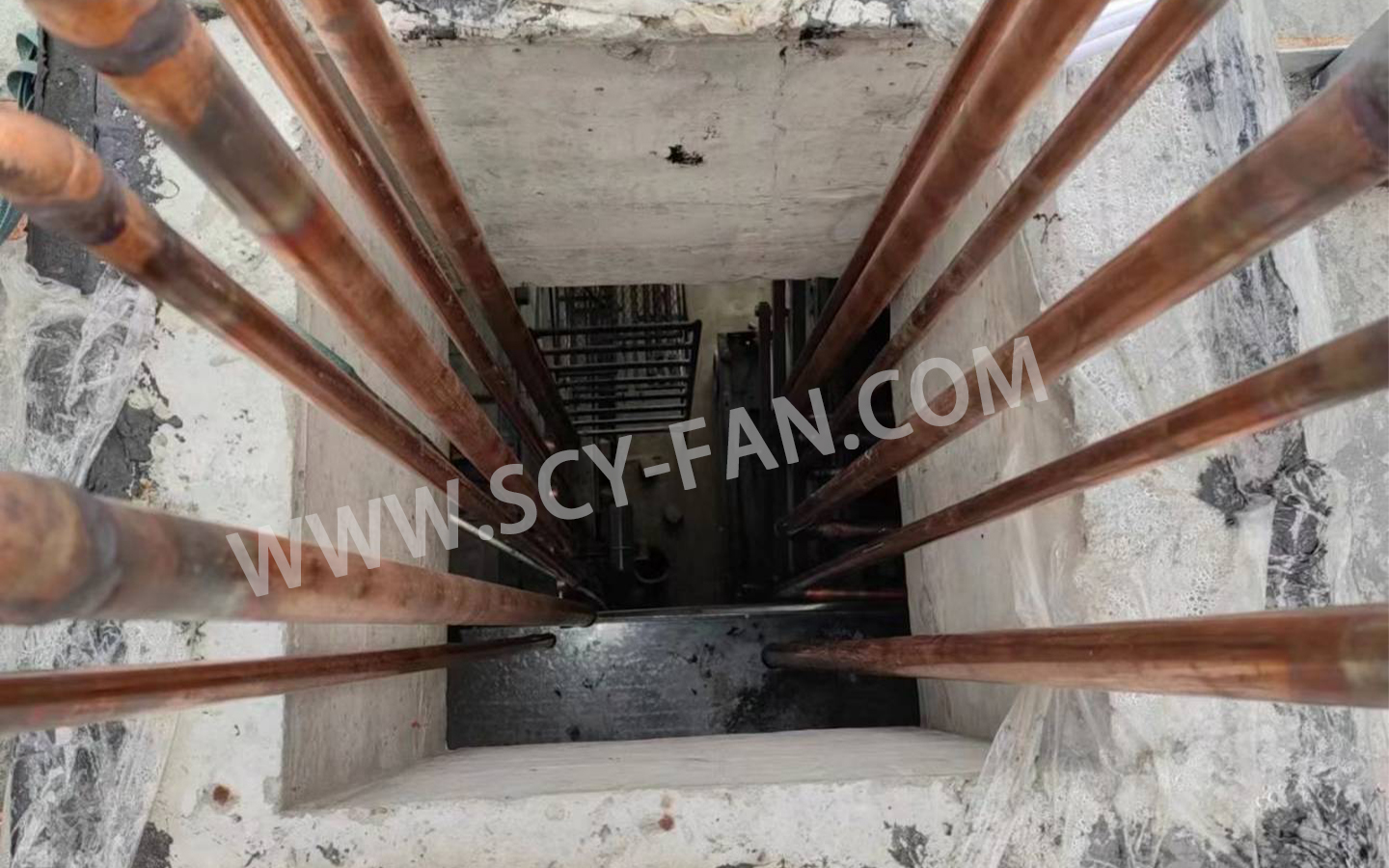
Cleaning of chilled water pipeline is essential prior to use as welding debris and other foreign matter commonly remain in the pipeline during installation processes which can cause pipeline blockages and equipment damage. Firstly, the fan coils on each floor and the inlet valves of the air conditioning mainframe must be closed, while opening the supply and return water loop valves. Then the circulation pump is turned on and left to run for 3-5 hours. Finally, the water in the system is drained and the filters of each fan coil and air conditioning mainframe are cleaned one by one.
Data collection of pressure drop in chilled water pipes and the system total pressure drop is necessary. All inlet and outlet valves of fan coils and air conditioning mainframes must be opened, and the circulation pump turned on to cycle at designed pressure for a certain amount of time, while measuring the pressure drop of each branch pipe and the total pressure drop of the circulation pump. Then, the system water pressure is increased to the debugging pressure (1.6KPa or 16kg for both hot and cold systems, based on design requirements), and the circulation pump is closed for at least 24 hours to enable measurement of the pressure drop of each branch pipe and total pressure drop of the circulation pump. Through collecting these data and comparing with designed data, any errors which occurred during the design and installation process can be identified and corrected.
- Debugging of cooling system
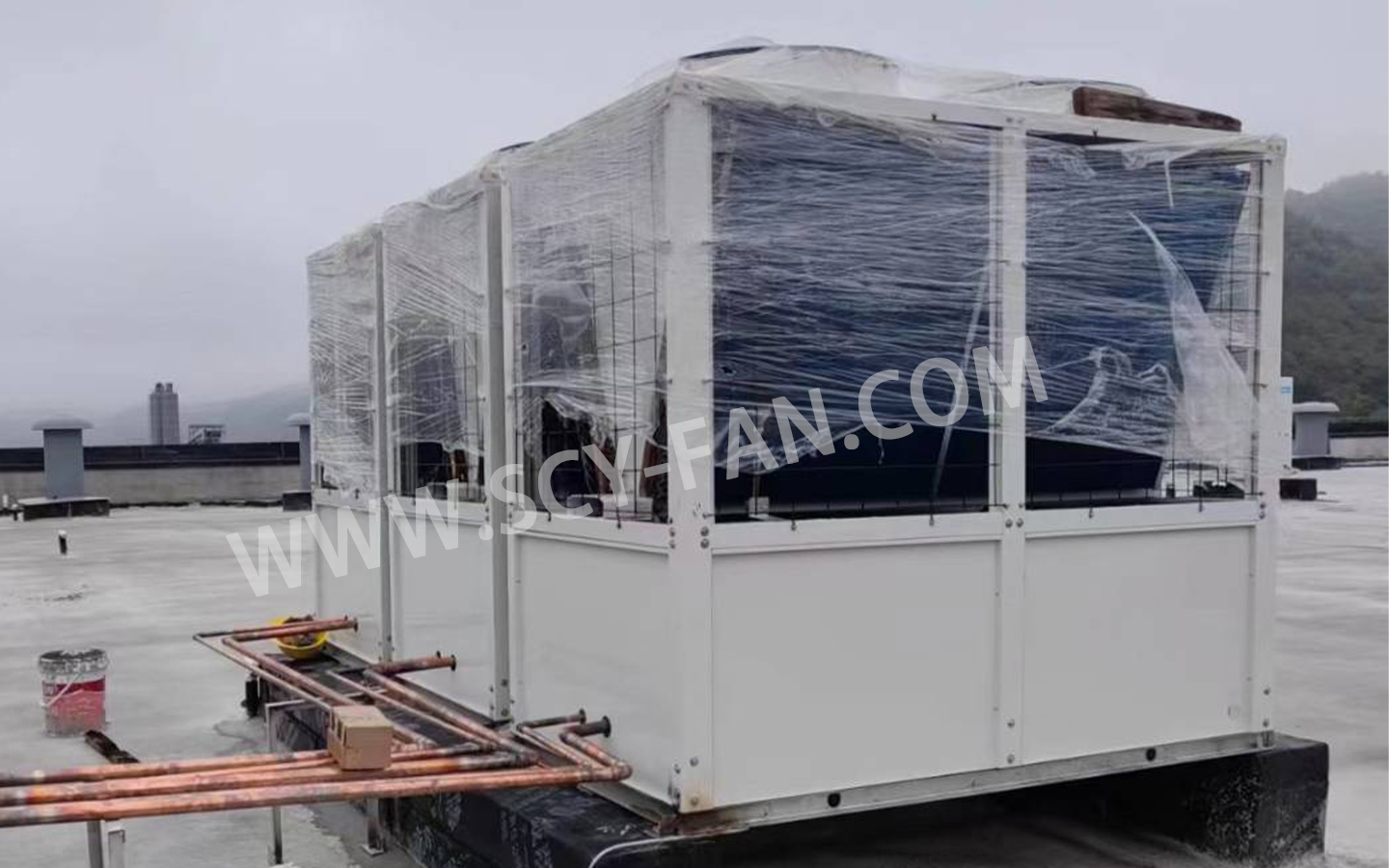
Cleaning of cooling pipeline is very similar to cleaning of chilled water pipeline. If there is no filter on the pipeline, it is recommended to install filters at the inlet and outlet of the air conditioning mainframe and cooling tower. This is because the open running cooling tower has a high possibility for water pollution which can easily lead to precipitation inside the condenser.
Debugging of the cooling tower, being a crucial part of the cooling system, firstly requires checking the availability of a smooth power supply. Due to the numerous fans on the cooling tower, it is easy to mistake the wiring during installation, so the power supply needs to be confirmed available. Then, turning on the fans and observing the rotation speed and direction from a close distance is necessary. Incorrect wiring should be checked when the fans do not rotate, wiring missing a phase should be checked when the rotation speed of fans is slow, and wiring order should be replaced when the fans rotate in the wrong direction. The uniform water distribution and blockages of the cooling water distribution system need to be observed. Finally, whether the liquid level control valve of the cooling tower is working properly when the water level rises or falls must be observed, and whether the control valve can quickly close when the water level reaches the upper limit needs to be checked.
- Debugging of End Devices
Fan coil unit is the main end device of central air conditioning system. When debugging, it’s important to first check if the model of the fan coil unit is correct. Then, turn on the speed control switch of the fan coil unit and adjust it from low to high gradually, while measuring the wind speed at the outlet of the unit. If no change in wind speed is observed, check if there is any issue with the speed control switch wiring. If wind speed doesn’t increase gradually, but decreases instead, then the wiring order of the speed control switch may be reversed. After confirming that the wind speed is normal, it’s necessary to check the air direction if it’s favorable for return air. The angle of the air direction can be adjusted by adjusting the outlet-blade of the fan coil unit. After the fan coil unit has been turned on for a while, observe if the condensate flows from the unit’s drainage tray into the system’s condensate pipe. If there’s any overflow of the condensate, it indicates that the slope of the air conditioning system’s condensate pipe is insufficient and needs to be corrected in time.
New air handling unit debugging is also critical. Since the new air handling unit is designed to treat outdoor air by cooling it down to appropriate temperature and humidity levels for indoor use, the rotational speed of the fan and air volume are key parameters for adjustment. In addition to the air handling unit, the air duct system must be also checked for proper function. Since the supply air duct of the new air handling unit is easily polluted during installation, air blowing should be conducted to clean the duct and then test if the ventilation valves or other devices in the duct system are operational and if the air pressure at the new air outlet meets the design requirements.
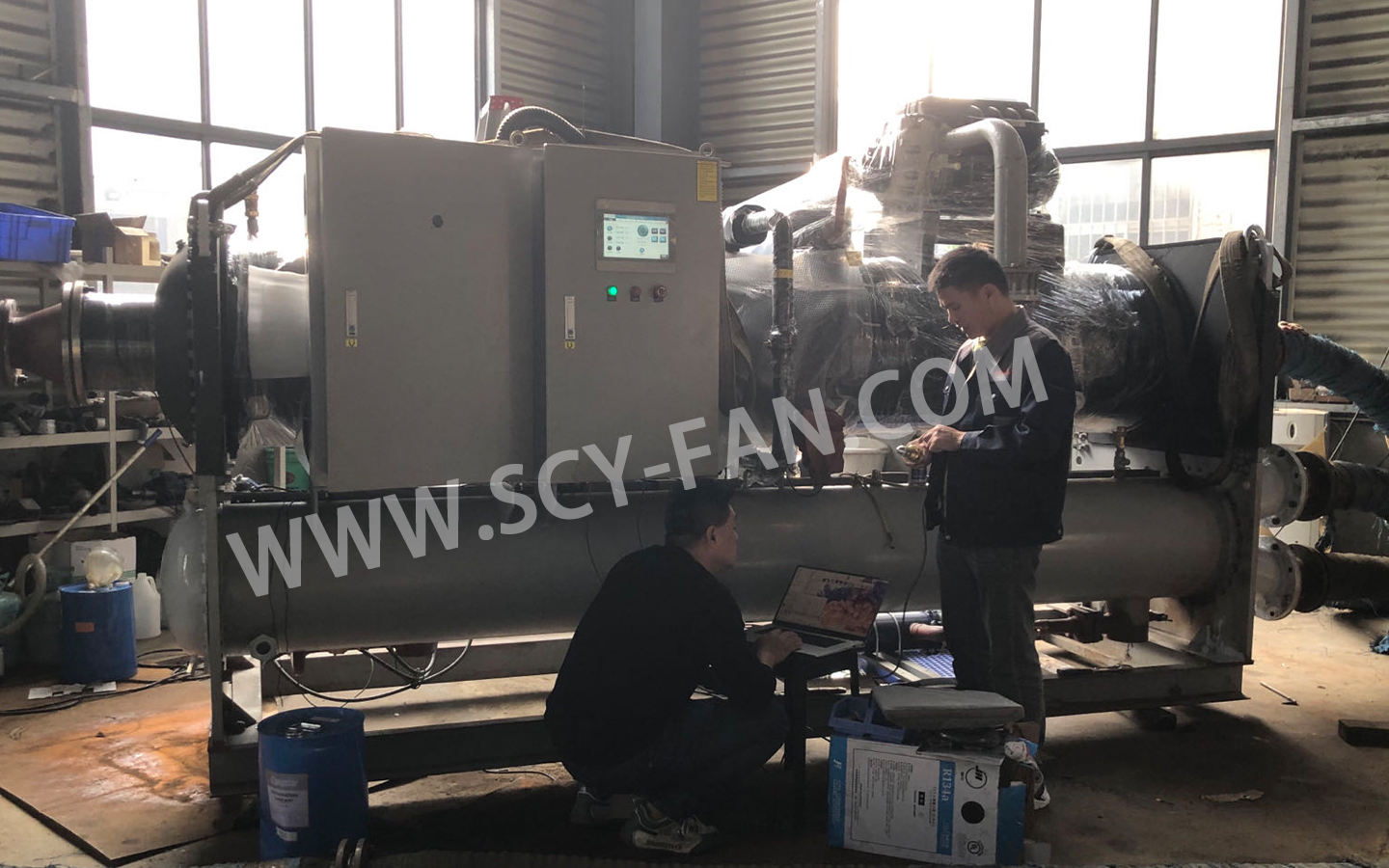
- Debugging of Air Conditioning Mainframe
The central air conditioning mainframe is the core of the entire system and is usually calibrated by the supplier or professional technical personnel. The air conditioning mainframe can be divided into two main types: electric refrigeration compression unit and lithium bromide refrigeration unit. The electric refrigeration compression unit includes some widely used types, such as centrifugal compressor, screw compressor, and piston compressor.
- Debugging of Auxiliary Equipment
The film-forming water processor is an equipment installed in the chilled water system to protect pipes from corrosion. The inlet and outlet of the device are equipped with valves, and during the water circulation, it’s necessary to check if they are properly opened and closed.
For the circulating water pump, its model should meet the design requirements. The pump’s lift is generally determined by the height of the building floor, and the flow rate is generally determined by the system load and volume. Since the flow rate is a variable, a frequency converter is generally added before the pump for energy conservation, with the water pump’s flow rate controlled by changes in temperature at the end devices. The calibration of the water pump is generally conducted in two stages:
In the first stage, the pump’s power supply device is checked to ensure its reliability and safety;
In the second stage, the water pump is turned on for operation, and parameters such as lift, flow rate, seal performance, and noise are measured. If the pressure gauge pointer trembles greatly, the system should be checked for air and pump leakage. If the noise and bearing temperature increase, the pump must be stopped immediately for inspection of bearing wear and oil deficiency in the bearing chamber.
For the water tank, before the system is put into use, the inlet and outlet valves of the tank and automatic devices (including water level indicators) should be tested for proper function. It’s necessary to check if the water source leading to the tank is unimpeded. If it’s from tap water, water pressure must be checked if it meets the requirements. If the water source comes from ion exchange equipment, it’s necessary to ensure that the equipment is supplying water properly.