Español
 Русский
 Tiếng Việt
 中文
中文 suomi
suomi Français
 Português
 English
 Deutsch
 Français
 Español
 Italiano
 Português
 Pусский
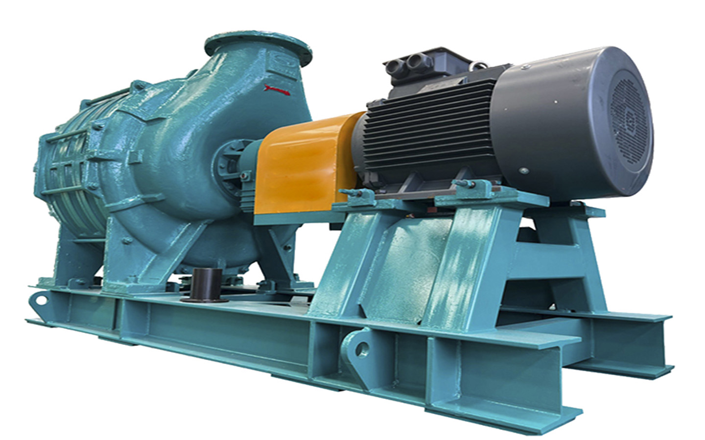
The multi-stage centrifugal blower manufactured by Zibo Decent Machinery Co., Ltd. is defined by its unique design of the main unit, accessories, and supports. The accessories incorporate several parts such as elbows, mufflers, filters, general-purpose wire mesh filters, and low- to mid-range filters that are fit for specialized purposes like microporous aeration, among others. Once you have a clear understanding of the structure of the blower, let’s proceed to look at the specific sequence of steps that should be followed while starting up the multi-stage centrifugal blower. To initiate the process, commence by cleaning the drain pipe and pump, contact the monitor, and central control room, turn on the electric heater, and examine the parameters. Read on to get the complete starting sequence for the multi-stage centrifugal blower.
What are the key structural features of multi-stage centrifugal blowers?
Multi-stage centrifugal blowers find wide application in various industrial sectors such as smelting blast furnaces, iron-making furnaces, coal washing jigs, mine flotation, sewage aeration, chemical gas production, and transportation of gases. They can also be used for moving other different gases. This series of blowers exhibits several key features, including high efficiency, low noise, smooth operation, no pulsation, a broad stability zone, clean, dry, oil-free gas, minimal wear and tear of parts, and easy to install, operate, and maintain. But, what are the notable structural characteristics of multi-stage centrifugal blowers?
The multi-stage centrifugal blower comprises three sections:
1. Host part: This part features the blower host, motor (universal, outdoor, explosion-proof), host, and motor coupling co-located, and host and motor direct coupling.
2. Accessories: This part includes elbows, mufflers, filters, general-purpose wire mesh filters, special-purpose low- and mid-range filters (microporous aeration, etc.).
3. Accessories: This part contains the fan inlet butterfly valve (manual type, electric type), motor control starting cabinet, flexible joint D series, single suction double support structure. It adopts a coupling transmission method, and when viewed from the motor side, the blower rotates clockwise. Two types of fans exist, high-speed and low-speed. The main shaft adopts a steel shaft design with a non-contact zigzag seal that offers excellent sealing performance, no wear or heat, and isolation of the motor valve base from the casing.
The principal working mechanism is similar to that of multi-stage centrifugal fans. Air enters the inlet guide vane regulator from the blower suction pipe. The main drive motor is connected to the speed-increasing gear through a coupling. The speed-increasing gear drives the high-speed rotating three-element semi-open impeller to work on the gas. The gas is subsequently released through the diffuser, scroll chamber, exhaust muffler, and diffuser tube. Air volume adjustment is possible by adjusting the imported guide vanes on the single-stage high-speed centrifugal blower that does not influence wind pressure. The fan shaft power can be reduced to achieve energy savings. Since the wind pressure may significantly decrease during frequency converter adjustment, single-stage high-speed centrifugal fans do not typically require frequency conversion to regulate air volume.