Español
 Русский
 Tiếng Việt
 中文
中文 suomi
suomi Français
 Português
 English
 Deutsch
 Français
 Español
 Italiano
 Português
 Pусский
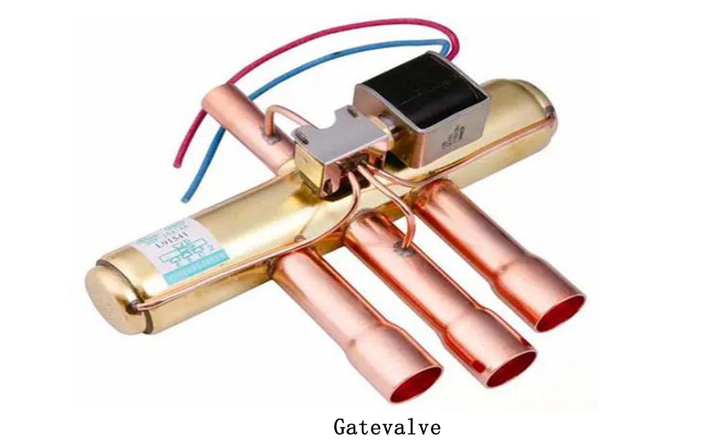
Four-way valve, the term for hydraulic valve, is a control valve with four oil ports.
Four-way valve working principle:
When the solenoid valve coil is in a power-off state, the pilot slide valve moves to the left driven by the compression spring on the right side. The high-pressure gas enters the capillary tube and then enters the right piston chamber. On the other hand, the gas in the left piston chamber is discharged. Due to the pressure difference between the two ends of the piston , the piston and the main slide valve move to the left, so that the exhaust pipe is connected to the outdoor unit pipe, and the other two pipes are connected to form a refrigeration cycle.
A gate valve is a valve that uses a gate plate as an opening and closing component and moves vertically along the axis of the valve seat to achieve opening and closing actions.
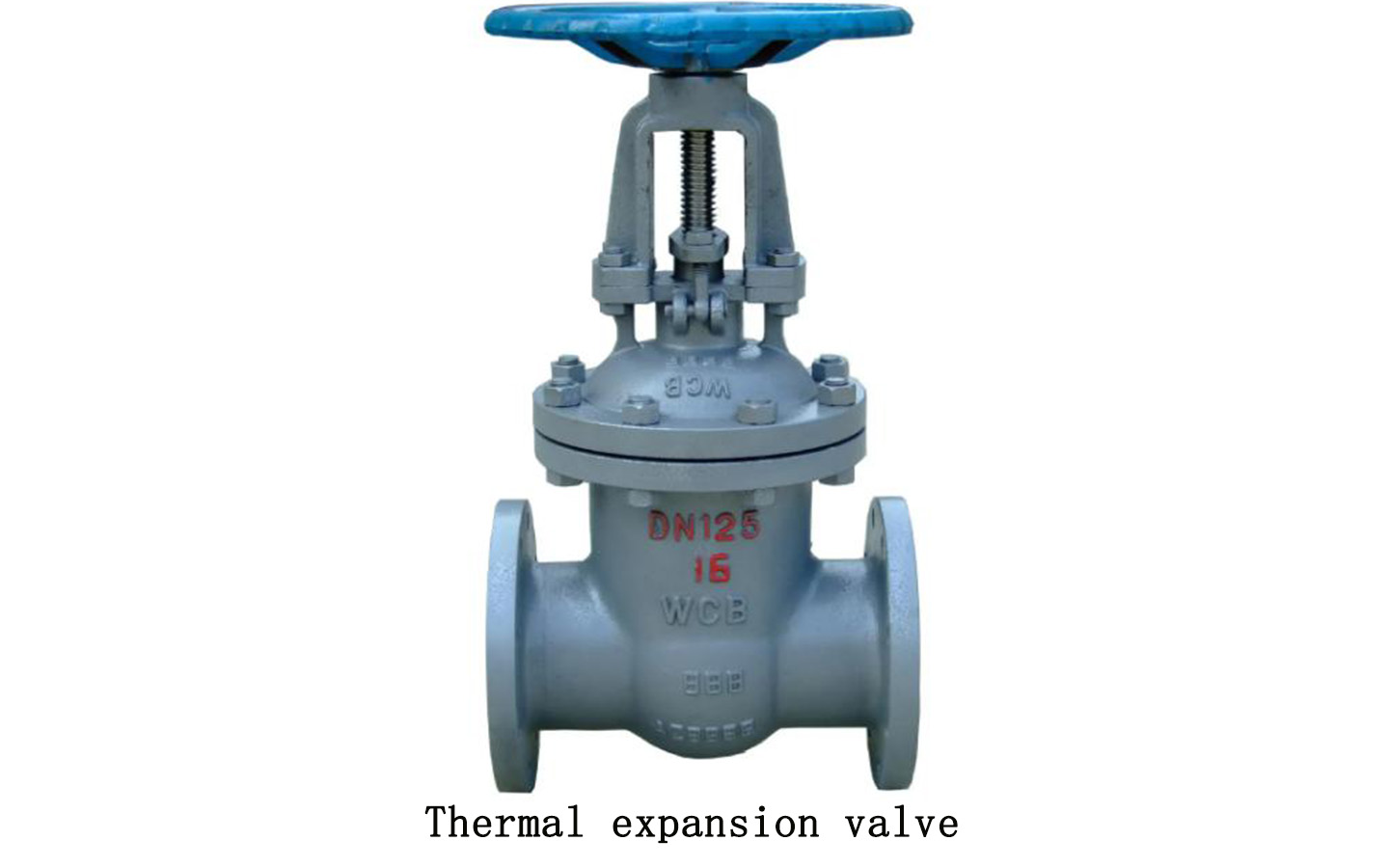
The thermal expansion valve controls the refrigerant flow into the evaporator by controlling the superheat of the gaseous refrigerant at the evaporator outlet.
Function of the thermal expansion valve: The thermal expansion valve realizes throttling from the condensing pressure to the evaporation pressure, while controlling the flow of refrigerant; the thermal expansion valve can supply liquid to the evaporator in the best way to ensure the stability of the superheat of the refrigerant steam at the evaporator outlet , the temperature sensing bag must be in good contact with the suction pipe of the compressor to accurately sense the suction temperature of the compressor. It is usually filled with the same refrigerant as the inside of the refrigeration system, so that the pressure fed back through the temperature sensing bag is It is the saturation pressure of this type of refrigerant corresponding to the compressor suction temperature; the expansion valve ensures that when the operating environment changes (such as changes in heat load), the optimal and optimal liquid supply method for the evaporator is achieved, and the temperature sensing The filling amount of the bag is only corrected based on the complete evaporation of the liquid refrigerant in the temperature sensing bag at a certain temperature. This is equivalent to specifying a pressure for the feedback pressure from the temperature sensing bag above the expansion valve diaphragm. The upper limit is because if the surface temperature of the tube wall continues to increase, it will only increase the temperature of the gaseous refrigerant inside the temperature sensing bulb (in a superheated state), and the pressure will basically no longer change.
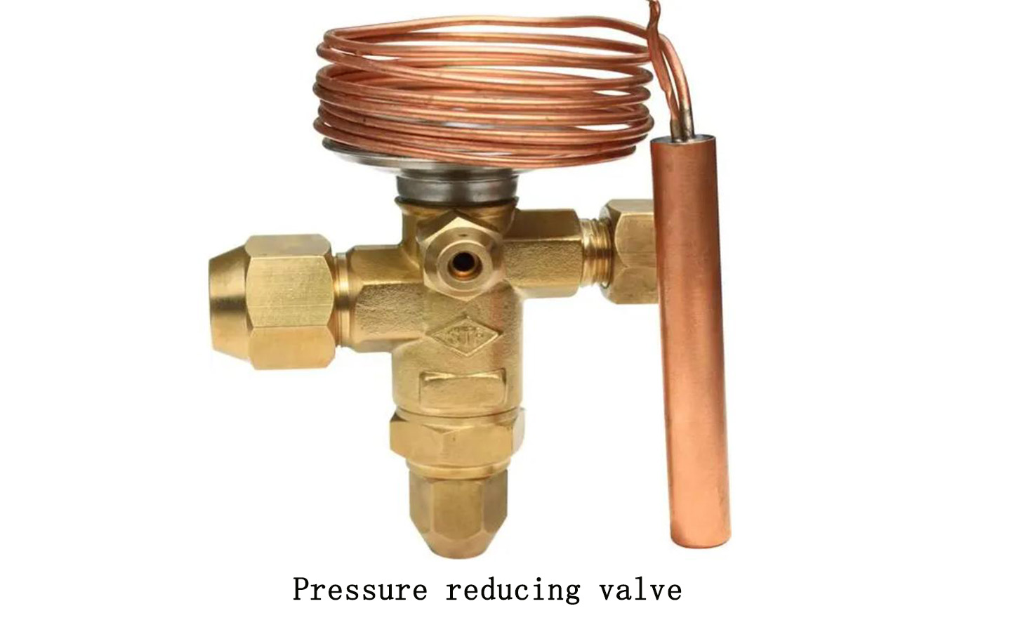
A pressure reducing valve is a specialized device that automatically reduces the working pressure of a pipeline. It can reduce the higher water pressure in the pipeline in front of the valve to the level required in the pipeline behind the valve.
Pressure reducing valve function:
The basic working principle of the pressure reducing valve is to reduce the water pressure by relying on the local resistance of the flow channel in the valve to the water flow. The range of the water pressure drop is automatically adjusted by the membrane connecting the valve disc or the difference in water pressure between the inlet and outlet on both sides of the piston.
Pressure reducing valve construction type:
There are many structural types of pressure reducing valves. In the past, the common ones were diaphragm type, inner spring piston type, etc.
Pressure reducing valves usually have various specifications such as DN50~DN100. The working pressures in front and behind the valve are <1MPa and 0.1~0.5MPa respectively, and the pressure regulation range error is ±5%~10%.
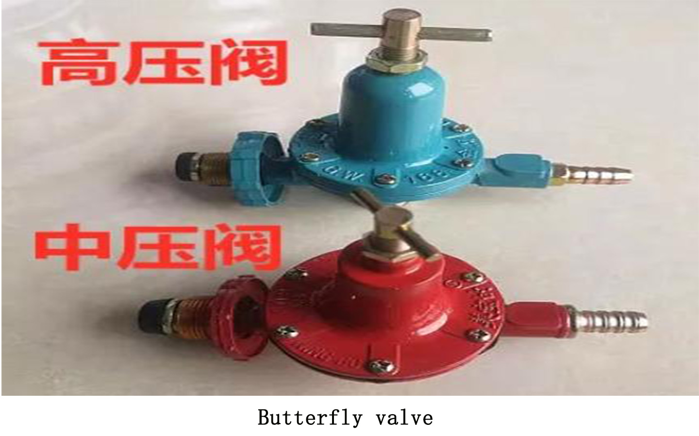
Butterfly valve definition:
Also known as flip valve, it is a kind of regulating valve. It refers to a valve whose closing part (valve disc or butterfly plate) is a disc and rotates around the valve axis to open and close. It mainly plays the role of cutting off and throttling on the pipeline. effect.
Butterfly valve application:
Butterfly valves can be used for switch control of low-pressure pipelines, and are suitable for transporting various corrosive and non-corrosive fluid media in engineering systems such as generators, coal gas, natural gas, liquefied petroleum gas, city gas, hot and cold air, chemical smelting, power generation and environmental protection. On pipelines, used to regulate and cut off the flow of media.
Butterfly valve classification:
Handle butterfly valve, turbine butterfly valve, pneumatic butterfly valve, electric butterfly valve, etc.
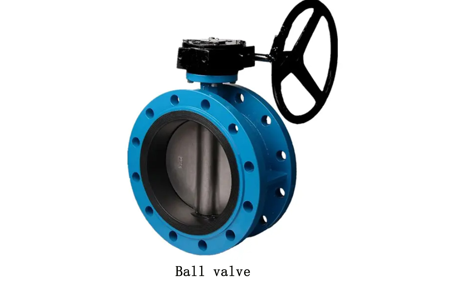
Ball valve definition:
Ball valve refers to a valve that uses a ball with a circular through hole as the opening and closing part, and the ball rotates with the valve stem to achieve the opening and closing action. The standard GB/T21465-2008 “Valve Terminology” defines it as a valve in which the opening and closing parts (ball) are driven by the valve stem and rotate around the axis of the square ball valve.
Ball valve working principle:
It can also be used for the regulation and control of fluids. The hard-sealed V-shaped ball valve has a strong shear force between its V-shaped ball core and the metal valve seat with hard alloy surfacing. It is especially suitable for fiber-containing and tiny solid particles. materials and other media. The multi-way ball valve can not only flexibly control the confluence, divergence, and flow direction switching of media on the pipeline, but can also close any channel and connect the other two channels. This type of valve should generally be installed horizontally in pipelines.
Ball valve classification:
Pneumatic ball valve, electric ball valve, manual ball valve.
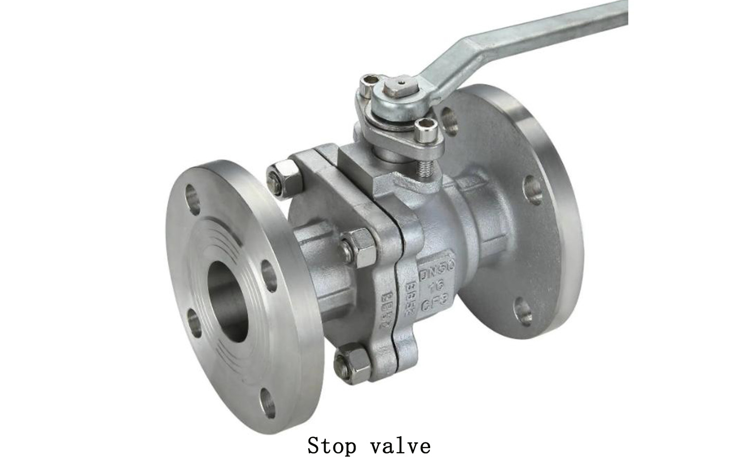
Stop valve definition:
Globe Valve, also known as stop valve, is a forced sealing valve and is one of the most widely used valves.
Globe valve principle:
The globe valve relies on the pressure of the valve stem to make the valve disc sealing surface and the valve seat sealing surface closely fit to prevent the flow of the medium. Since the medium is only allowed to flow in one direction, it is directional during installation. Globe valves can be divided into DC globe valves, angle globe valves, plunger globe valves, upper threaded stem globe valves, lower threaded stem globe valves, etc. They are durable, have low opening height, are easy to manufacture, and are easy to maintain. , not only suitable for medium and low pressure, but also suitable for high pressure characteristics.
Advantages of stop valve:
1. Simple structure, convenient to manufacture and maintain.
2. The stroke is small and the opening and closing time is short.
3. Good sealing performance and long service life.
In addition, the stop valve also has shortcomings, such as poor adjustment performance and a large amount of force required for switching. It is not suitable for media with particles, high viscosity, and easy coking.
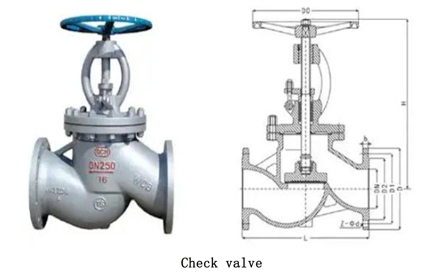
Check valve definition:
Check valve is also called one-way valve or check valve. The main function is to prevent the medium in the pipeline from flowing back. The opening and closing parts rely on the force of medium flow to open or close by themselves. The check valve only allows the medium to flow from one direction to the other direction, and does not allow reverse flow to prevent accidents, so the check valve is also called a check valve.
Installation Precautions:
The biggest difference in appearance between the check valve and other valves is that the check valve does not have a valve shaft and does not require manual operation or electric control. During installation, care should be taken not to allow the check valve to bear weight. Large check valves are independently supported; the direction of medium flow should be consistent with the direction on the valve arrow.
Check valve classification:
Check valves can be divided into lift type, swing type, butterfly type and diaphragm type according to their structure. According to the connection method, it is divided into three types: threaded connection, flange connection and welding.
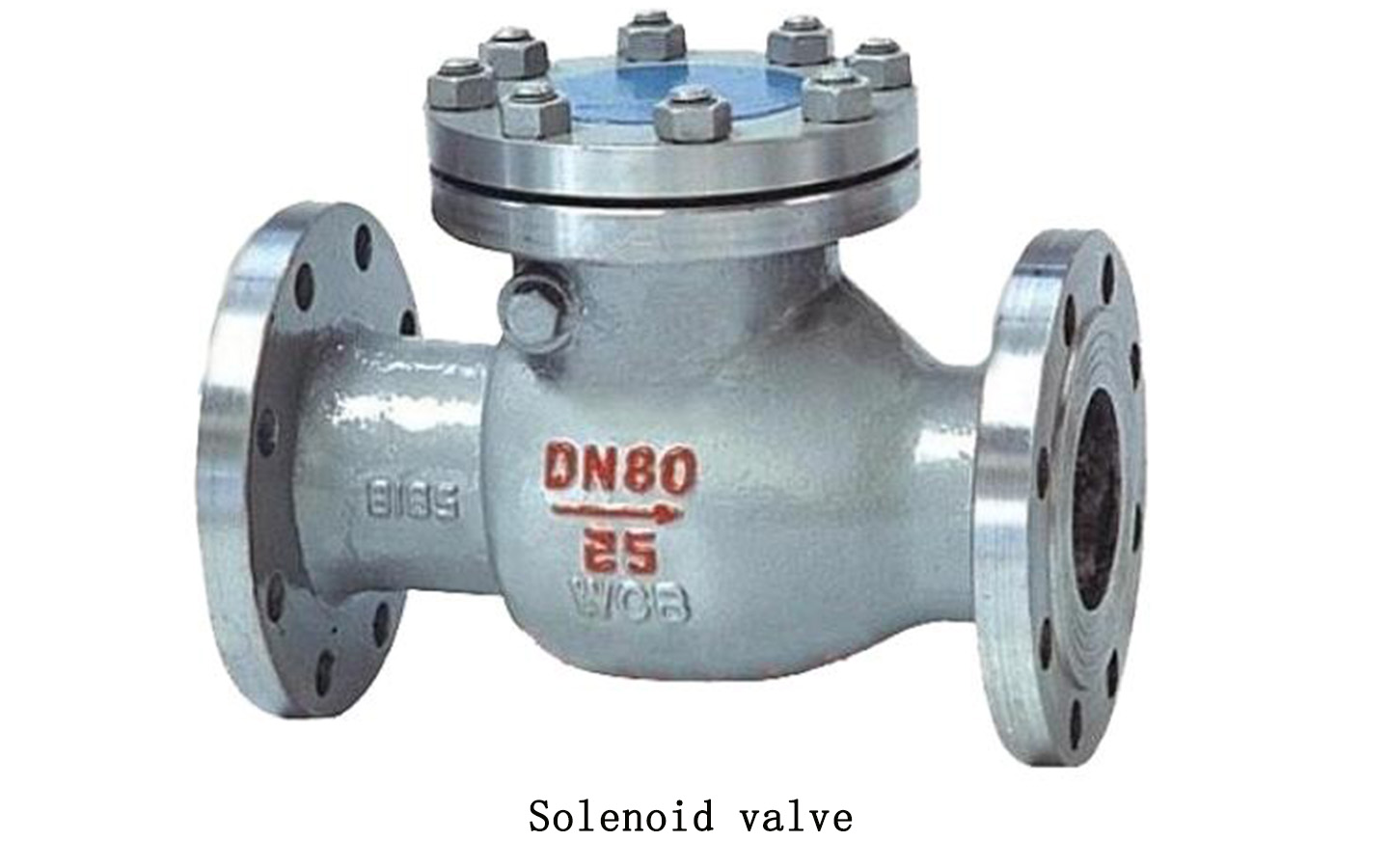
Solenoid valve definition:
Solenoid valve is a basic component of automation used to control fluids and is an actuator; it is not limited to hydraulic and pneumatic. Solenoid valves are used to control the direction of hydraulic flow. Factory mechanical devices are generally controlled by hydraulic steel, so solenoid valves are used.
Working principle of solenoid valve:
There is a closed cavity in the solenoid valve, with through holes at different positions. Each hole leads to a different oil pipe. There is a valve in the middle of the cavity, and two electromagnets on both sides. Whichever side of the magnet coil is energized, the valve body will be attracted. Wherever it goes, the movement of the valve body is controlled to block or leak different oil drain holes. The oil inlet hole is normally open, and the hydraulic oil will enter the different oil drain pipes, and then push the oil steel through the pressure of the oil. The piston drives the piston rod, and the piston rod drives the mechanical device. In this way, the mechanical movement is controlled by controlling the current of the electromagnet.
Solenoid valve application:
Solenoid valve (Electromagnetic valve) is an industrial equipment controlled by electromagnetism. It is a basic component of automation used to control fluids. It is an actuator and is not limited to hydraulic and pneumatic. Used in industrial control systems to adjust the direction, flow, speed and other parameters of the medium. Solenoid valves can cooperate with different circuits to achieve expected control, and the control accuracy and flexibility can be guaranteed. There are many types of solenoid valves. Different solenoid valves play a role in different positions of the control system. The most commonly used ones are one-way valves, safety valves, directional control valves, speed regulating valves, etc.
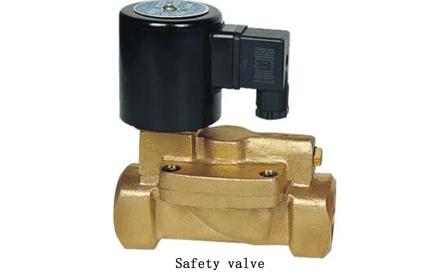
Safety valve definition:
The safety valve is a valve that protects the system from damage due to excessive pressure. Once the medium pressure exceeds a set value, the safety valve will automatically open to achieve safety protection.
Safety valve classification:
According to the structure, safety valves can be divided into hammer lever type, spring type and pulse type.
Heavy hammer lever type safety valve: It uses the lever principle to use a small heavy hammer to obtain the force acting on the valve through the amplification of the lever. The force acting on the valve is changed by moving the position of the heavy hammer or changing the position of the heavy hammer. Cracking pressure, as shown on the left. Its advantages are simple structure and accurate adjustment, and it is suitable for high temperature and high pressure occasions such as boilers and containers with high pressure. The disadvantage is that the heavier loading mechanism is prone to leakage due to vibration, and it is difficult to close and maintain tightness after being blown open by pressure.
Spring micro-lift safety valve: The force of the compression spring is used to balance the force acting on the valve disc. The compression amount of the spring can be changed by adjusting the nut on it, which can be used to adjust the opening pressure of the safety valve. The advantages are light and compact structure, high sensitivity, unlimited installation position and can be used on mobile pressure vessels. As shown in the left figure below, the disadvantage is that the elastic force of the spring increases with the increase in compression, so the pressure loading the valve will increase with the increase in compression, which directly prevents the safety valve from opening quickly.
Pulse safety valve: It is composed of a main valve and an auxiliary valve. The pulse action of the auxiliary valve drives the work of the main valve. Its scope of application is narrow and its structure is complex. It is only suitable for boilers and pressure vessels with large safe discharge volumes.
Among these three types of safety valves, the spring slightly lifted safety valve is the most commonly used.
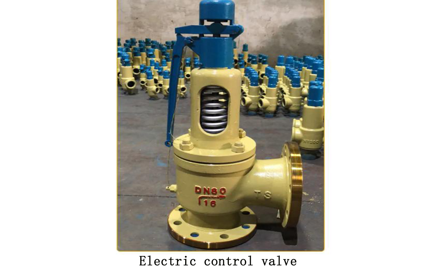
Electric control valve definition:
The electric regulating valve is composed of an actuator and a valve body located below the actuator. The actuator and regulating valve can be used after being connected and combined, and can only be used after installation and debugging.
Principle of electric regulating valve:
By receiving the weak signal (0-10v or 4-20mA) from the building or industrial controller, the valve opening is changed to adjust media flow, temperature, pressure and other parameters. Realize automatic adjustment and achieve energy saving effect.
Precautions:
When selecting an electric regulating valve, it is best to choose one with manual control if possible. This can prevent the valve from not opening or closing normally due to circuit failure. As shown in the picture, the threaded disc on the top of the electric control valve is the manual adjustment disc.
When using the electric control valve, pay attention to regular inspections to check whether the actuator is faulty and whether there are any abnormalities in the connection between the actuator and the valve shaft. This ensures its safe and efficient operation. Generally speaking, it should be checked every half month.
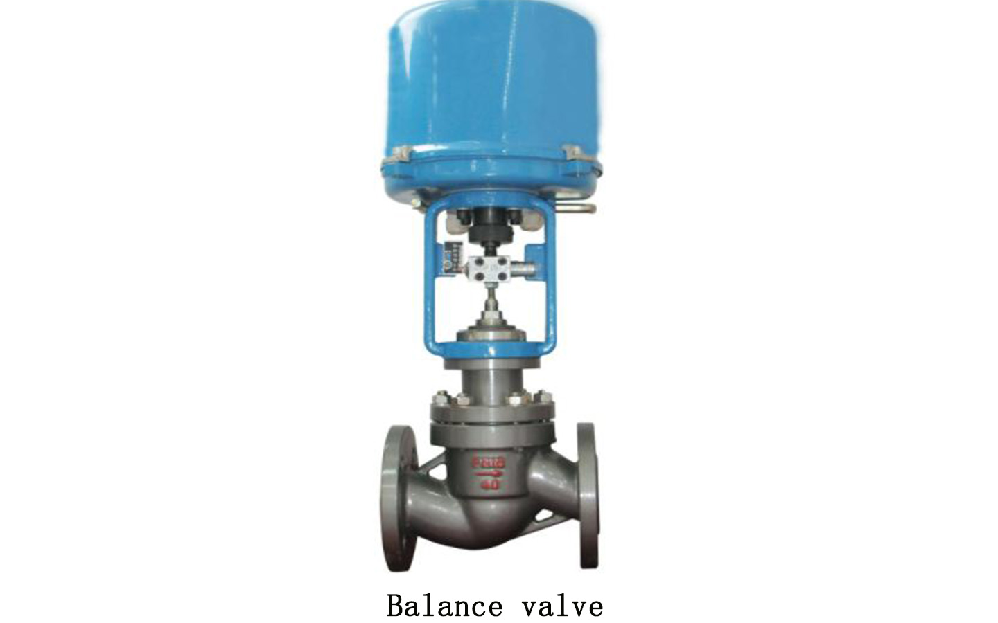
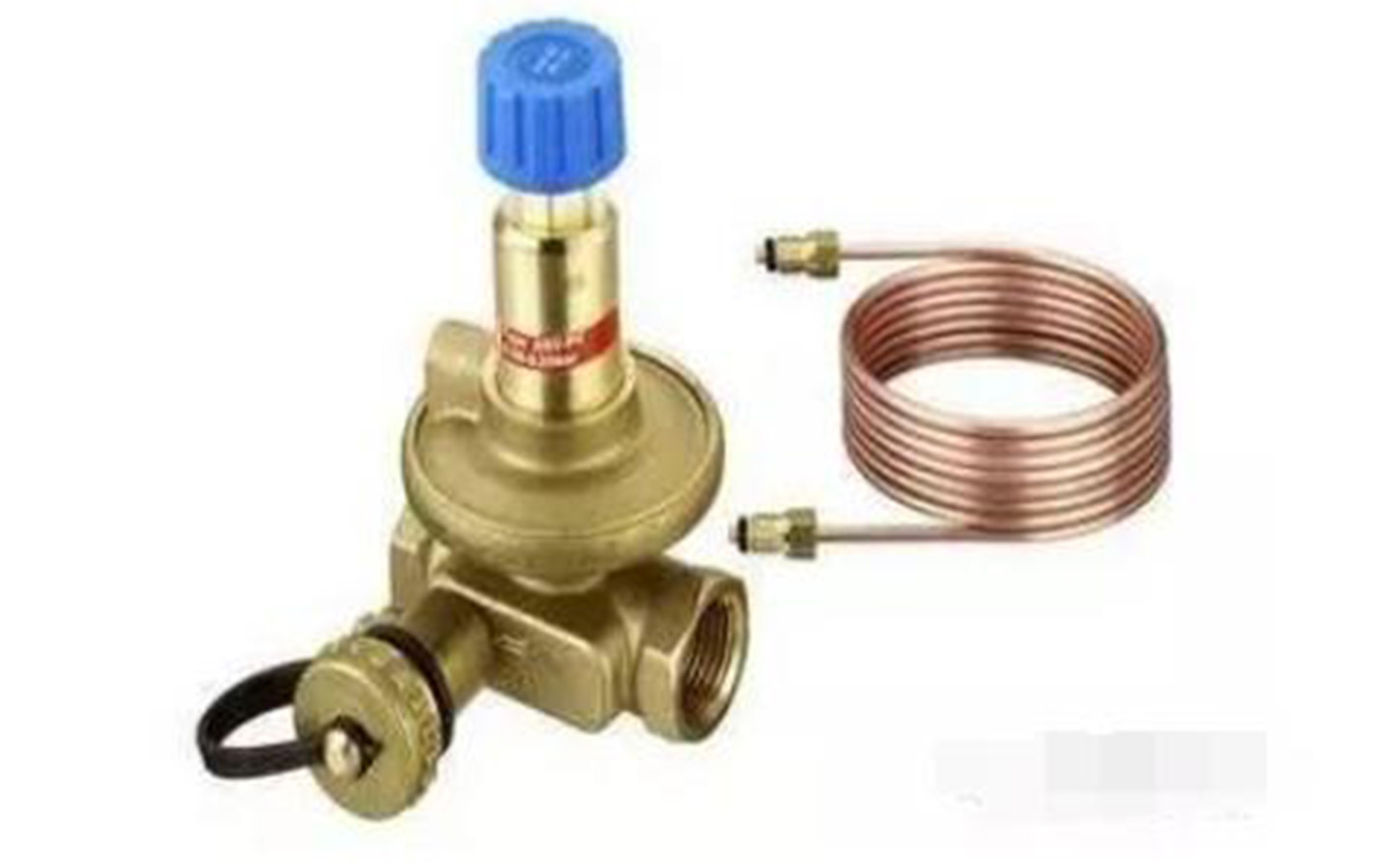
Balance valve definition:
The balance valve is a valve with special functions. It has good flow characteristics, has a valve opening indicator, an opening locking device and a small pressure measuring valve for flow measurement. Use a special smart instrument to input the valve model and opening value, and the flow value flowing through the balance valve can be directly displayed based on the measured pressure difference signal. As long as a balance valve of appropriate specifications is installed in each branch and user inlet, And by using a special intelligent instrument for one-time debugging, the flow rate of each user can reach the set value.
Balance valve features:
1. Ideal adjustment performance;
2. Excellent cut-off function;
3. Open status display accurate to 1/10th of a circle;
4. The theoretical flow characteristic curve is an equal percentage characteristic curve;
5. National patented opening and closing locking device;
6. There is a certain flow coefficient corresponding to each full circle. During debugging, as long as the pressure difference between the two ends of the valve is measured, the flow rate flowing through the valve can be easily calculated;
7. PTFE and silicone sealing, reliable sealing performance;
8. Internal components are made of YICr18Ni9 or copper alloy, which has strong corrosion resistance and long service life;
9. The valve stem can be lifted and lowered internally, so there is no need to reserve operating space.
10. It is a combination valve.