Español
 Русский
 Tiếng Việt
 中文
中文 suomi
suomi Français
 Português
 English
 Deutsch
 Français
 Español
 Italiano
 Português
 Pусский
 1. Condensate overflow analysis
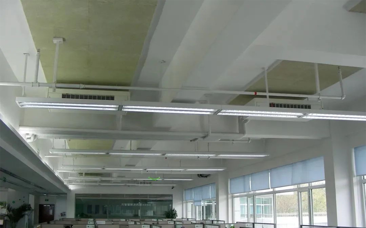
Overflow of condensation water from fan coil units is a common fault of centralized air conditioning systems in summer. It often occurs in hot and humid weather and will cause unnecessary damage to air-conditioned rooms:
a) Water damage to the ceiling panels will damage the indoor building decoration, and the maintenance workload of the fixed ceiling will be greater.
b) If the condensation water overflow is not discovered in time, it will damage the office appliances.
c) Special rooms that require 4 hours of air conditioning and unattended electrical equipment rooms usually cannot use the fan coil system or VAV system in the office area. The air conditioning system is often configured separately. The overflow of condensed water from the fan coil will cause serious damage to these rooms. The economic losses are even greater.
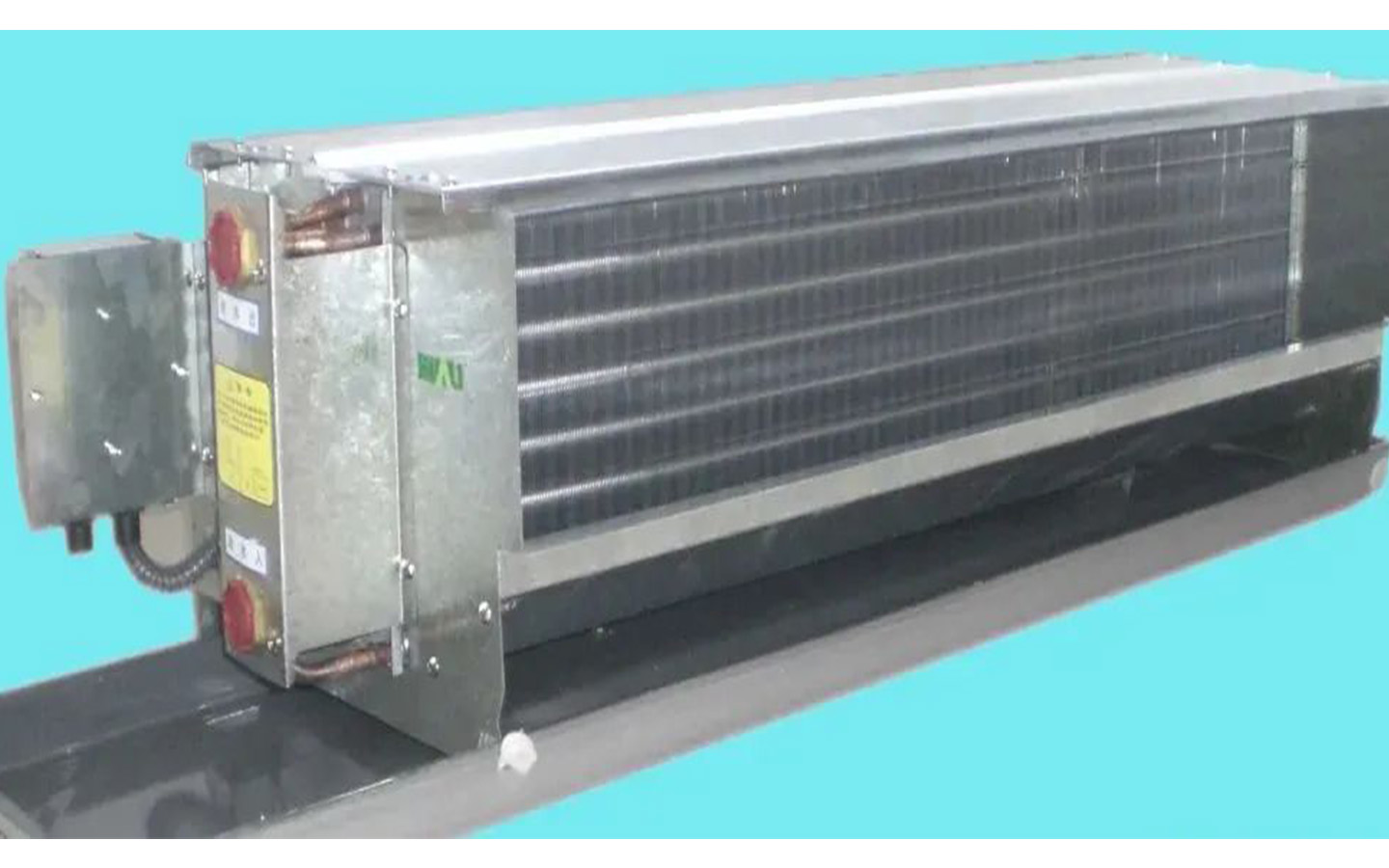
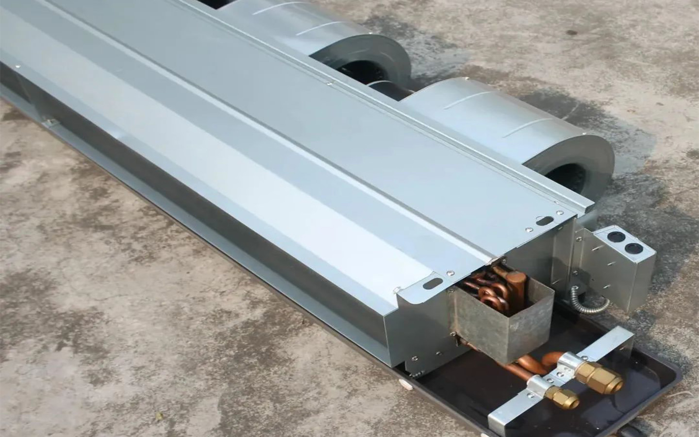
The condensate overflow from the fan coil is caused by the blockage of the condensate pipeline connected to the fan coil condensate pan. Since the fan coil unit operates under wet conditions in summer, the dust and fine fibers on the surface of the heat exchange coil will be washed down by the condensation water and deposited in the condensation water pan, causing bacteria to multiply and produce gelatinous dirt, which will gradually block the condensation. water pipe. The overflow of condensed water from fan coil units is caused by equipment manufacturing, engineering design, construction and operation management.
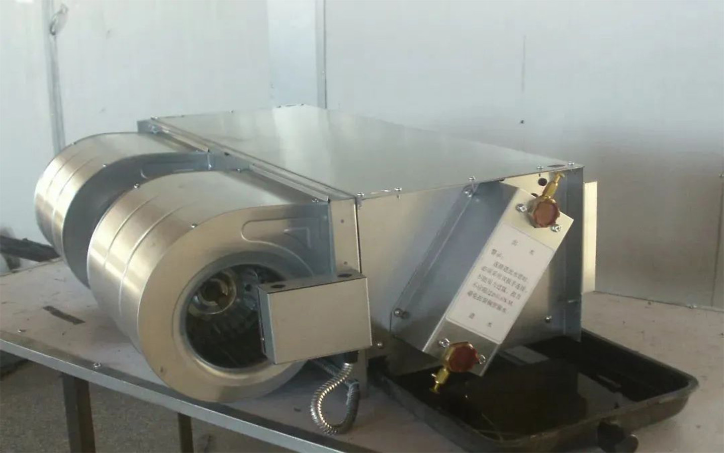
Fan coil units are semi-finished products that must be matched with controllers and electric water valves from other manufacturers to handle air. Therefore, few people consider the design of fan coil units as a whole. For example, after long-term use of fan coil units, the condensate pipes may become blocked, resulting in There is a potential danger of condensate overflow, but it does not have a self-control alarm function.
At present, the product manual only emphasizes that dust and debris will block the condensate pipeline and should be removed in time. There are no specific self-control measures to prevent the condensate from overflowing, shifting the responsibility to maintenance personnel, and manual maintenance and upkeep are inevitable. There will be omissions. Therefore, after a centralized air-conditioning system using a fan coil unit has been running for several years, condensate overflow failures often occur. During maintenance, the only way to repair the leakage is to fix it, and the work is relatively passive.
During the engineering design, the distance between the fan coil unit in the guest room of the hotel and the bathroom is short, and the drainage slope is easy to realize. However, for the centralized air conditioning system of large public buildings using fan coil unit as the terminal device, the horizontal distance of the condensate pipe is too long. , too many elbows, coupled with the low floor height, it is difficult to achieve a drainage slope. Therefore, the fan coil condensate piping system itself of many buildings has certain inherent deficiencies.
During the construction of the air-conditioning system, the fan coil condensate pan is not installed at an adequate inclination, the condensate water pipeline is long and there are few brackets, and the pipe rigidity cannot be guaranteed. The slope of the condensate water pipeline during construction is not enough, etc., which will cause the condensate water to be discharged poorly during system operation. In addition, if the condensate water pipe is constructed without a cleaning port, the condensate water pipe cannot be cleaned during use.
If operation and maintenance personnel fail to thoroughly clean all fan coils and condensate pipes on a regular basis, condensate water from the fan coils will also overflow. Theoretically, the condensate water pan of the fan coil should be cleaned once every summer before use, and again after 2 to 3 months of operation. The air-conditioning zones in many large office buildings run from March to December, and the electrical equipment rooms are provided with cooling throughout the year. Therefore, the condensate pipes of the fan coils need to be cleaned 3 to 4 times a year to avoid clogging.
Since the fan coil unit is concealed in the ceiling, the cleaning operation is very inconvenient. At the same time, when cleaning the fan coil unit, it must also ensure that various equipment inside and outside the ceiling are intact and cannot affect the normal work of indoor personnel. Therefore, all fan coil units must be truly implemented Regular cleaning is more difficult.
In summary, overflow of condensate water from fan coil units is unavoidable. If the equipment manufacturer can add a water-full alarm to the condensate water pan of the fan coil unit, this problem can be effectively eliminated.
2. Self-control measures to prevent condensation water from overflowing
Since the condensate pan of the fan coil is very shallow, a mechanical float-type overflow prevention device is obviously not suitable. The digital integrated circuit water full alarm introduced in the literature [Huang Jichang, Guo Jizhong, Zhang Haigui. 300 examples of digital integrated circuit applications. Beijing: People’s Posts and Telecommunications Press, 2003] is more suitable. Its circuit principle is shown in Figure 1.
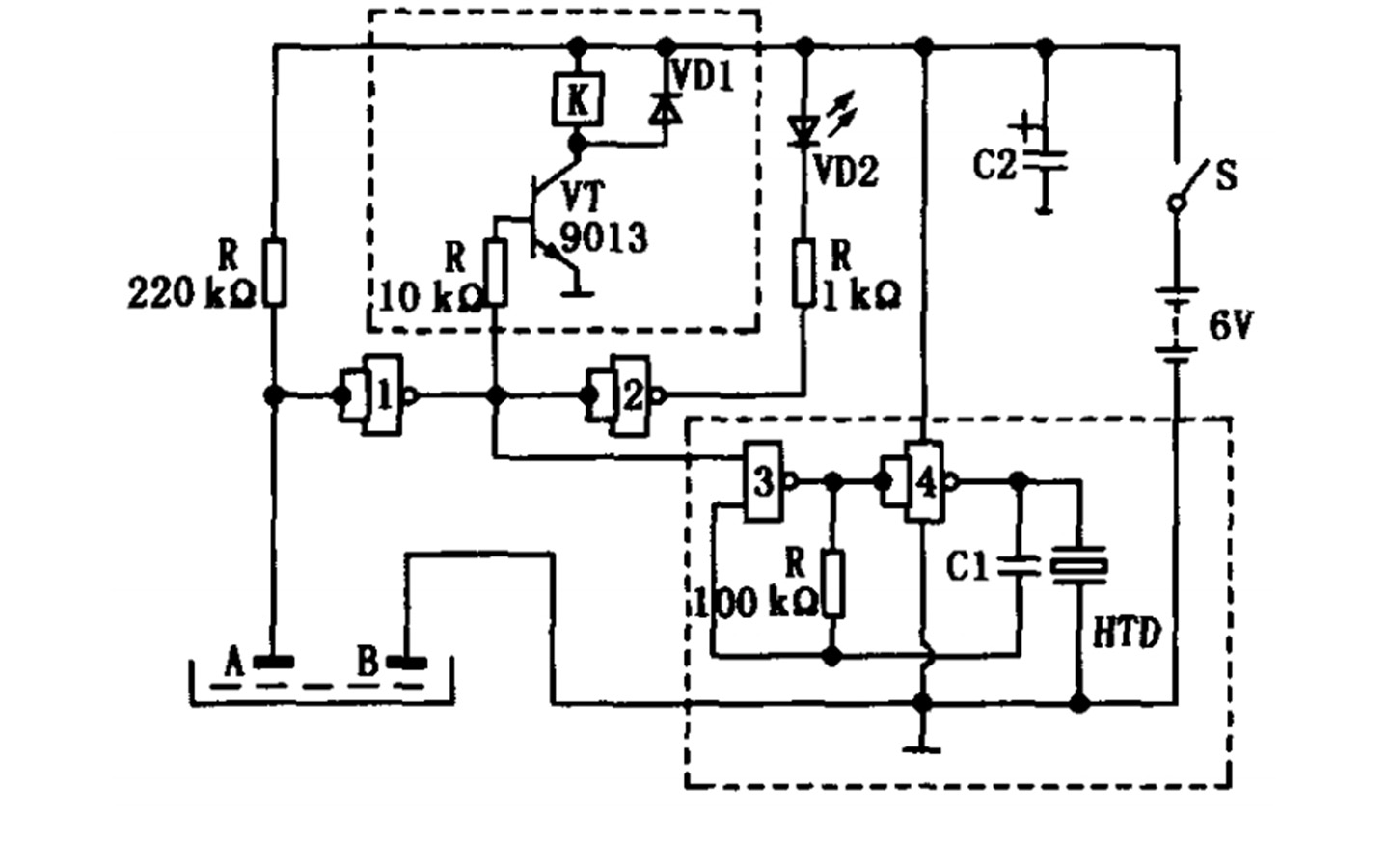
A and B in the figure are two horizontally arranged detection pole pieces, used to detect the water level in the condensate pan. When the condensate is not full, A and B are open circuits because they are not in contact with water. The input terminal of NAND gate 1 is high potential “1”, the output terminal is low potential “0”, the transistor V T is in the cut-off state, and the relay K It does not pull in, the input terminal of NAND gate 2 is low potential “0”, the output terminal is high potential “1”, the light-emitting diode VD2 does not light up and alarms, the output terminal of NAND gate 3 is also high potential “1”, and the output terminal of NAND gate 3 is also high potential “1”. NOT gate, the multivibrator composed of 4 stops vibrating, and the buzzer H TD does not work.
When the water level in the condensate pan reaches the set height of the sensor, the resistance between detectors A and B becomes smaller, causing the input end of NAND gate 1 to change from high potential “1” to low potential “0”, and the output end changes from “1” to “0”. When “0” changes to “1”, the transistor V T is turned on, the relay K is closed, its contacts cut off the power supply of the fan coil, and the fan coil stops working. The output terminal of NAND gate 2 changes from “1” to “0”, causing the light-emitting diode VD2 to light up and alarm. Similarly, the multivibrator composed of NAND gates 3 and 4 starts to vibrate, and the buzzer H TD sounds an alarm.
The alarm uses CMOS digital integrated circuit technology, and its principle and structure are very simple. Four NAND gate circuits are solidified on the same chip. This chip is very common, and its unit price is equivalent to that of the diodes and transistors used, both of which are less than one yuan. Therefore, the cost of the electronic components of the water-full alarm is less than 10 yuan, and the actual production cost is also low, which will not significantly increase the manufacturing cost of the fan coil unit.
The schematic diagram of the water full alarm circuit in Figure 1 is just an example. Developers can also design simpler circuits according to their own needs. In Figure 1, NAND gate 1 is responsible for the signal detection function of high and low potential conversion after the water full resistance becomes smaller. Transistor VT, NAND gate 2 and NAND gates 3 and 4 are responsible for cutting off the power of the fan, lighting alarm and sound respectively. There are three follow-up functions of the alarm. These three functions can be completely changed according to the actual needs of the user. The alarm indication signal can even be added to the current fan coil control panel.
3. Other measures
Since the fan coil unit and air-conditioning water system pipelines are on the ceiling of the office area of the office building, there is a risk of water leakage. Therefore, it is recommended that when designing air conditioners and secondary decoration, the system should be arranged at the end of the room as much as possible to maximize the safe use space without flooding.
Operation and maintenance personnel should insist on regularly inspecting and cleaning the condensate water pans and condensate water main pipes of all fan coil units. The maintenance workload of the fan coil air conditioning system is much greater than that of the VAV system, so sufficient maintenance personnel must be arranged.